Education - Part 3D1
Track
Track
Once ROW is established, trackage (rail lines) may be constructed. This involves several steps, including preliminary testing and evaluation of the land on which the track is to be laid (including environmental concerns), detailed design and preparation of engineering drawings and so on. Keep in mind the fact that trackage needs to embody as little inclination or declination as possible (no up and down hill). It also must be concerned with radius of curvature and other factors that affect the velocity at which trains may operate. After all, time is money.
The following discussion depends on several sources, including American Railway Engineering and Maintenance-of-Way Association (AREMA), CSX Transportation (CSX), Mississippi Information Website (ICRR), Kansas City Southern (now Canadian Pacific Kansas City (CPKC)) (KCS), Union Pacific Railroad (UP) and Federal Railroad Administration (FRA). See for example Federal Railroad Administration, Track and Rail and Infrastructure Integrity Compliance Manual, Volume II Track Safety Standards, Chapter 2 Track Safety Standards Classes 6 through 9, March 2018, 114 pp. These reference sources specify the standards and constraints that must be adhered to in the construction of trackage.
Track Bed
The basic structure of the track bed is suggested in the following illustration. Because of the weight of trains passing over the railway, the foundation must be firmly established, adequate drainage provided and a sound layer of sub-ballast (fine crushed stone) and ballast laid down.
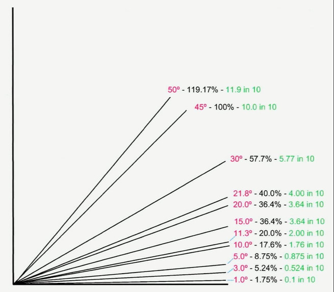
In addition, the grade must be carefully established. Grade (gradient, slope, pitch, incline, rise) is the inclination or declination from level. Grade can be expressed in various equivalent ways, as shown in the following diagram. Trains operate best on level track. Grade, for most of railroad history, was kept to near 0 degrees (0°) by means of cuttings, tunnels, bridges and fills (see Roadbed Components, later on).
Today, the use of diesel-electric and electric motive power means that grade is of lesser concern but can by no means be ignored. For many years, the "ruling grade" was considered to be 1% (the steepest incline navigable by existing motive power). Today the ruling grade is considered to be 2.2% although steeper grades are in regular use where motive power is sufficient. Grade is as important going down hill (declination) as going up (inclination), because of the need for braking (see Braking in Transport).
Rails on high-speed routes (typically 200 km/h or greater) are canted inward by 5% from vertical regardless of grade to insure the least wear on the rails and a better fit of wheel tread to rail.
Grade is also important on curves where it is referred to as cant. In essence, the rails are banked (outside rail higher than inside rail) to reduce the lateral force on the rails around a curve due to centrifugal force and allow for faster travel around the curve. Cant is especially important on passenger lines for the comfort of passengers. Too much cant on freight lines can cause extra wear on the inside rail because of the greater weight of freight trains.
Modern railway construction tends to favor the ballastless approach to track laying in which a concrete base (similar to a highway) is poured, upon which concrete or steel ties or sleepers are laid, often on a resilient pad, to support the rails and reduce vibration. This approach is most commonly used in railway terminals and on high-speed rail lines.
Ties (Sleepers)
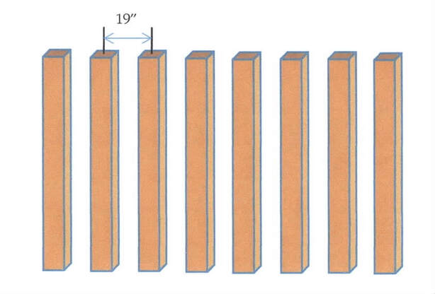
The next step in railroad construction is placement of the ties (sleepers) upon which the rails rest. For most of railroad history, ties were made of wood having approximate dimensions of 7 x 9 x 102 inches (17.8 x 22.9 x 259 cm). Such ties suffered from weather, heavy use and frequent need of replacement. While wooden ties are still in use, modern track, laid on gravel beds or a ballastless foundation, uses prestressed concrete ties (sleepers) or steel ties. Wooden ties are usually laid with spacing at 19 inches (48-49 cm) on centers; concrete or steel ties with spacing of 24 inches (58 cm) to 30 inches (72.6 cm) on centers. This spacing reduces the number of ties needed per mile of track.
Rails
Rails are made of steel. Over the years, research has enabled the steel used to be improved (metallurgy) and the rolling of it into rails improved to reduce failure due to internal flaws in the steel structure.
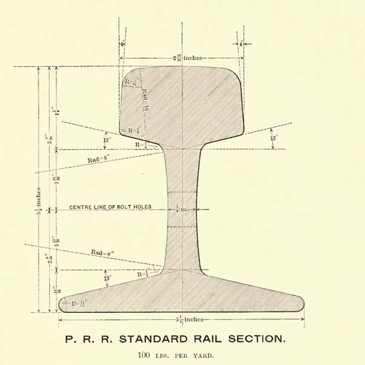
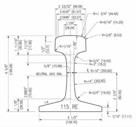
In the United States, rails have a cross-section such as specified in the drawings below. The rails are called flat-bottom rails. The particular shape of rails, as well as the composition of the steel used, varies with the load and speed to be supported and other factors such as weather and loading.
Rail Classification
Rails are classified according to their weight per unit distance and to their cross-section. In the drawings, the PRR rail has a weight of 100 lbs/yard (49.6 kg/meter) of rail, while the 115 RE rail has a weight of 115 lbs/yard (57 kg/meter). Rails are manufactured in a variety of classes for use in particular applications, such as main-line freight, sidings and high-speed rail. Today, rails are most often 115 or 132 pounds per yard (57.5 or 66 kg/m).
Rail Fastening
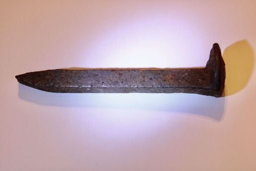
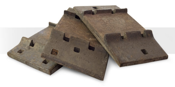
A rail may be fastened to a tie in a variety of ways. For many years, a rail was placed on a tie-plate (see below) then fastened to a tie with spikes of sizes from 9⁄16 to 10⁄16 inch (14 to 16 mm) square and 5½ to 6 inches (140 to 150 mm) long (see also Spikes, later on).
Screws have come be used since they hold better and can be applied mechanically.
Today, prestressed concrete or steel ties are often used in which the equivalent of tie plates are embedded in the tie. A rail is held in place by some form of clamp. See Fasteners for more detail.
Track Gauge
Tie plates (or other fasteners) are positioned on a tie so as to achieve the gauge the railroad operates on. Gauge (sometimes spelled gage) is a measure of distance between the rails forming a track. "Gauge" is also used for other measures, such as model railroad track (e.g., HO gauge, but more correctly HO scale), wire diameter, air pressure and so on. In railroading, gauge refers to the distance between rails of a track, measured from the inside of the head of the rail.
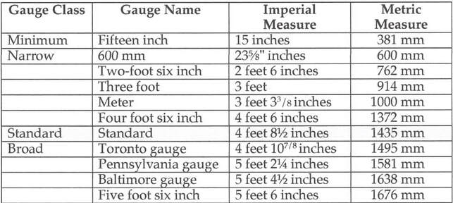
In much of the world, standard gauge, which is 4 ft 8-1⁄2 inches (1,435 mm), is used but there are several other gauges in use as well. The following table shows several railroad gauges that have been or are in use presently.
Gauge in Model Railroading
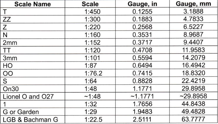
Today, model railroads are generally built to scale, the relationship between the model and its prototype. In essence, the modeler strives to make the model layout as realistic as possible, with structures, scenery, trucks and cars and all other components built to a standard scale. There are a number of scales in use, as indicated in the following table.
The above table shows the standard gauge of track for each model scale, to four decimal places. The Shannondell Model Railroad is based on HO scale, so the track gauge is effectively 0.65 inches or 16.5 mm. All other components of the SMR layout are dimensioned accordingly.
World wide, there are a number of organizations that support standards for model railroads. In North America, the National Model Railroad Association (NMRA) provides this service, while in Europe it is MOROP (an initialism derived from"MOdellbahn" and "euROPe"). Most railroad modelers conform to scale and gauge standards.
Spikes
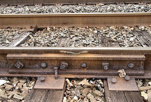
Use of spikes has engendered many references to them in song and folklore (we mention the golden spike, denoting the initial completion of Shannondell Model Railroad, in SMRC History). Today, when spikes are used, a special spiking machine does the job; in former times a spiker was expected to drive a spike with a spike maul in three blows. Given that each tie-plate required 5-6 spikes, the spiker had to drive a large number of spikes per mile of roadway. (No, John Henry was not a spiker but a miner.) The following photo shows the typical connections when wooden ties, tie plates, spikes and bolted rail are used.
Use of spikes has engendered many references to them in song and folklore (we mention the golden spike, denoting the initial completion of Shannondell Model Railroad, in SMRC History). Today, when spikes are used, a special spiking machine does the job; in former times a spiker was expected to drive a spike with a spike maul in three blows. Given that each tie-plate required 5-6 spikes, the spiker had to drive a large number of spikes per mile of roadway. (No, John Henry was not a spiker but a miner.) The following photo shows the typical connections when wooden ties, tie plates, spikes and bolted rail are used.
Track Classification
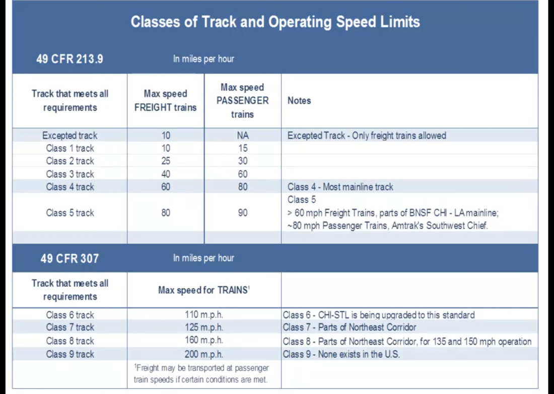
In the United States, track carries a classification that specifies the upper velocity limit permitted on the class of track. The classes and velocity limits are shown in the following table.
