Education - Part 5B6
Unpowered Railroad Cars - Car Construction
Construction Of Unpowered Railroad Cars
It is time to take a look at the actual construction of unpowered railroad cars. It is worth noting that "car" is short for "carriage". In many parts of the world, railroad cars are called wagons. Either term suggests that railroad cars (wagons) developed from existing wagons or carriages of a bygone era.
To build a flatcar, for example, a foundation frame is constructed of steel members such as I-beams, U-beams, tubular beams or something similar. The dimensions of these beams are determined by the load they are expected to support (up to 200,000 pounds or more).
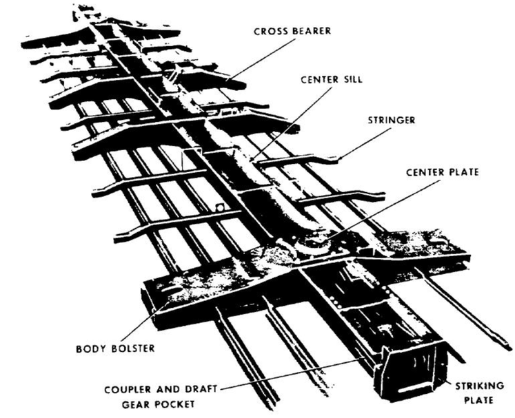
The following diagram gives an idea of the construction of the foundation frame of a flatcar. Details are available (for a fee) at Association of American Railroads, Safety and Operation, Manual of Standards and Recommended Practices (MSRP).
As the above illustration suggests, the end sill of the frame is about 10 feet long and must accommodate the coupler components (see following diagram). The foundation frame thus supports several under-frame components, including the coupler, body bolster and brake system
and above-frame components such as the decking, stake pockets, tie-downs, bulkheads and so on. Decking may be of steel or wood. All components must be situated so that weight symmetry about the long axis of the car is maintained.
Couplers
The coupler, as the name indicates, enables the unpowered cars to be connected to motive power and to each other. Freight trains of 100 cars are fairly common in the United States and other parts of the world (e.g., Mauritania, Australia, China). Longer trains are used but are not so common. Weight of the train must also be taken into account. Trains carrying 35,000 tons (70,000,000 lbs. or 31,751,466 kg) have been reported. Couplers must be strong enough to handle such massive loads.
Several types of coupler have been developed, including buffer and chain, link and pin, Albert coupler, Miller hook and platform, Norwegian, Lloyd coupler, Johnston coupler, bell-and-hook coupler and several others. In the United States, the Janney coupler is the standard and we limit our discussion to this type of coupler (now referred to as the Association of American Railroads (AAR) coupler).
Eli H. Janney invented the Janney coupler (also called knuckle coupler). Janney was awarded a patent for his invention in 1873 (U.S. Patent 138,405). This coupler is automatic in that no worker is required to be between cars during coupling and uncoupling.
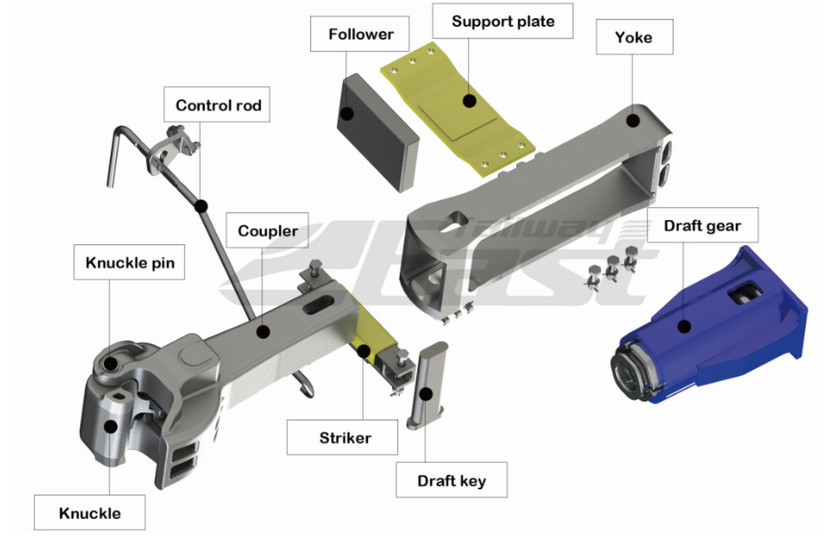
The coupler consists of three main parts, the knuckle with its shank, a coupler pocket and a draft (or draw) gear, essentially a shock absorber. The component parts are illustrated below. The purpose of the draft gear is to absorb the pushing and pulling forces caused by the motion of the cars of a moving train. Typical travel distance is about 3.5 inches. This "slack" or "play" means that on a 100-car train, the last car moves, relative to the first one, about 2-3 minutes later.
The coupler pocket is fastened between the two center sills and houses the coupler shank, the follower, the draft gear and the yoke. The yoke surrounds the follower and draft gear and is connected by a draft key to the coupler shank. The control rod serves to lift or drop the knuckle pin to permit uncoupling. The striker limits the travel of the knuckle toward the pocket.
The following illustration shows an un-powered car (top) coupled to a locomotive (bottom).
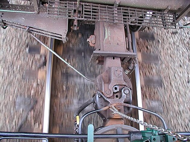
Photo showing coupling between a locomotive (front) and unpowered car (rear). The chain connects to a control rod that lifts a locking pin from the locomotive coupler; the control rod angled toward the left lowers the locking pin from the unpowered-car coupler (these control rods are inoperative when the train is in motion). The coupler pocket and part of the coupler shank are also visible (from Wikipedia)
Braking
Another important under-frame element is the braking system. We have mentioned braking of trains elsewhere on this Web site (see, for example, Caboose History under Railroad History). Under normal operation, braking is needed to adjust the velocity of a train to prevailing conditions (traffic, curves, weather, etc.). Until the advent of the Westinghouse Automatic Air Brake System (ABS), braking was a manual affair with attendant hazards to the life and limb of workers called brakemen.
In 1869, George Westinghouse was awarded U.S. Patent No. 124,405 for a railroad braking system that used compressed air to operate the brakes on each railroad car (technically a pneumatic brake system). Over the years, various improvements have been made to this system, which is now universally employed on trains around the world. The current system is briefly described in the following paragraphs.
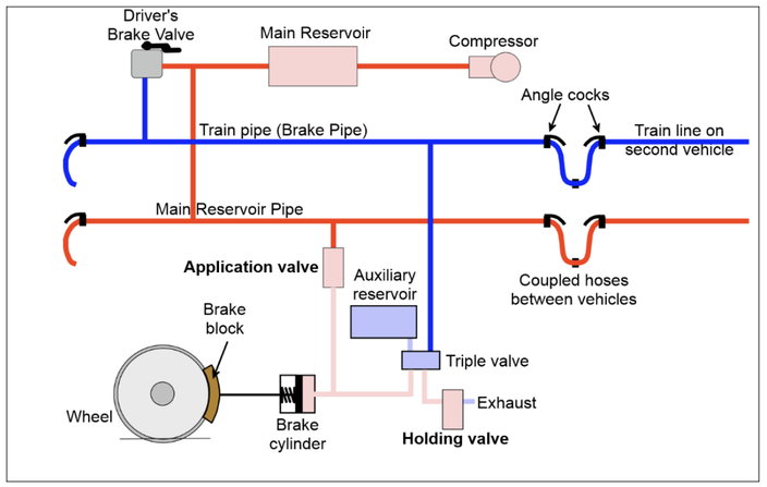
In a locomotive a compressor pump (see NYAB for example) produces compressed air at around 125–140 psi (8.6–9.7 bar; 860–970 kPa) which is stored in the main reservoir (in the locomotive), that supplies compressed air to a pipe, called the train line (also brake line) that extends the entire length of a train. The train line is connected to a triple valve on each car. See illustration below.
The locomotive brake valve (automatic or driver's brake valve), provides for braking at the command of the operator (driver). Automatic braking occurs when the pressure in the train line (brake line) becomes less than the pressure at the main reservoir. This reduction in pressure in the train line is achieved 1) by the operator moving the control lever on the locomotive (driver's) brake valve; 2) by some break in the train line (e.g., loose connection, puncture or separation).
The train line (brake line) is composed of both metal pipe traversing the length of each car and flexible hose lengths that connect successive cars. Flexible hose is connected to the metal pipe by means if an angle cock (shut-off valve). The flexible hoses of two adjoining cars are connected together by means of F-Type Gladhand fittings. The air brake system is only operational if the angle cocks at the end of each car all are open except the one at the front of the locomotive and the one at the end of the train.
A second line, called the main reservoir pipe, also supplied from the main reservoir, is used to supply pressurized air to reservoirs on each car of the train. This line continuously supplies air to the car reservoirs until equilibrium is achieved and maintained. This insures that car reservoirs are fully charged independent of the train line.
A car reservoir is a tank mounted on the under-side of each car. The tank has two compartments, one for service (normal braking) and one for emergency application. The car reservoir makes each car independent of all others in a train for braking purposes.
The car triple valve is the brains of the system and is divided into service and emergency parts. This valve is so named because it performs three main functions: 1) it allows air into a reservoir ready to be used; 2) it applies the brakes and 3) it releases the brakes. In so doing, it supports certain other actions (i.e., it 'holds' or maintains the brake application and it permits the exhaust of brake cylinder pressure (brake release) and the recharging of the reservoir during the release). In this way, the car reservoir is insured of pressure from both the main reservoir pipe and the car triple valve.
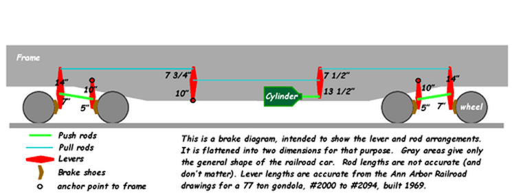
The object of all of this braking system is the car brake cylinder, that applies pressure to the brake pad assembly (see illustration below) to slow or stop the train. The assembly may serve 8 or 12 wheels (two 2-axel or 3-axel trucks). Modern railroad cars may use disc brakes rather than shoe or pad brakes. The result is the same: friction is developed which slows or stops the train.
Electronically controlled pneumatic (ECP) brakes are the most recent innovation wherein the brakes of all the cars and locomotives are connected by a kind of telecommunication network (either wired or wireless), which allows individual and direct control of the brakes on each car, and reporting to the driver (and dispatcher) the performance of each car’s brakes (and other conditions). Electronic control overcomes the problem of propagation delay when air pressure is reduced in the train line. This means that brakes are applied more rapidly (essentially instantaneously) along the length of a train and also that there is less wear on the draw gear (see Car Construction) at the ends of each car.
Railroads have been slow to convert their rolling stock to ECP because of the cost and because, as originally introduced, there was no method to mix cars equipped with ECP with cars having PCP (conventional pneumatic braking systems). However, Zeftron, Inc. developed a version of ECP that effectively dealt with this problem, as described in a report by the Federal Railroad Administration (FRA).
Finally, each individual railroad car is equipped with a manual brake wheel to brake a car when it is isolated from a train. ECP is designed to detect the state of manual brakes so as to avoid brake set when they should be released.
Truck or Bogie
The third important under-frame element on a railroad car is the truck (bogie). A truck is what provides the ability for a railroad car to move and to negotiate curves. There have been many truck designs implemented in various parts of the world. Here we describe trucks similar to those manufactured by Amstedrail. For a more modern design, see bogies.
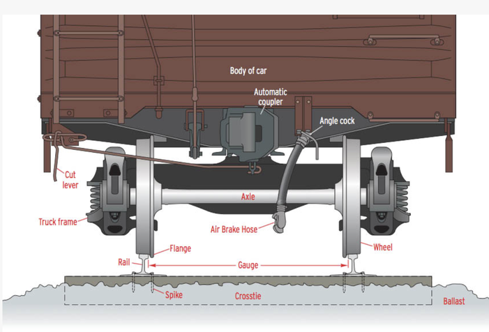
Each railroad car needs at least two trucks (but see Jacobs Bogies), each either of two or three axels. A 2-axel truck, together with a coupler and part of the braking system, can be seen in the following illustration.
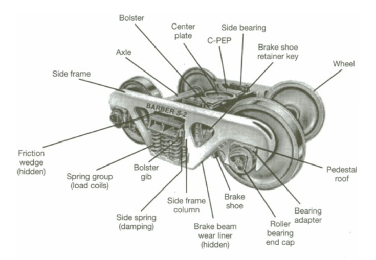
In this illustration the truck consists of an axel and two wheels supported by a truck frame that is attached to a truck bolster (large dark member behind the axel) that rests on coil springs. The truck bolster connects with a body bolster (dark under-frame member behind the coupler and end sill). The following illustration identifies the various components of a truck (bogie).
A typical unpowered car truck has five principal components, two axel/wheel assemblies, two side frames and a bolster. An axel/wheel assembly consists of an axel with two wheels press-fitted to it at the gauge of the track on which it will travel. A roller-bearing end cap, also press-fitted, terminates each end of the axel. The axel/wheel assembly supports, via gravity, the side frame at the bearing cap.
The side frame is a one-piece cast steel part that bridges the two axel/wheel assemblies and contains a central pocket in which a group of coil springs, called load coils, support the ends of the truck bolster.
The truck bolster consists of a heavy cast steel member that links the two side frames together at the correct distance for the gauge of track on which the truck will travel. The bolster sits on the load coils so as to cushion the railroad car that will rest on the truck bolster. The bolster and side frame are held together by means of friction wedges and bolster gibs. At the center of the bolster there is a circular center plate with a rim and a center pin (not shown). At either side of the center plate is a side bearing and C-PEP (center plate extension pad) that reduces hunting and sway.
In order to link a truck with the under-side of the foundation frame of a railroad car, the car must be equipped with body bolsters (one for each truck). A body bolster is a heavy-duty steel member that is attached to the foundation frame of the car. See following illustration.
At the center of the underside of the body bolster is a circular plate that fits into the truck center plate. A hole in the center plate accommodates the pin that protrudes from the truck center plate. The body bolster has side bearings (not seen in the illustration) that correspond with those on the truck bolster. That is the extent of the link between a car and a truck. Obviously, the trucks can pivot to facilitate travel over curves in the track. At the same time, it is clear that the linkage demands centering the mass of a load along the long axis of the foundation frame to prevent the car tipping over.
There is much more to the construction of unpowered railroad cars, but we have presented the basics. Further detail, along with standards, regulations and best practices may be obtained from individual railroad companies and in the United States, the Association of American Railroads (AAR), Federal Railroad Administration (FRA) and American Railway Engineering and Maintenance-of-Way Association (AREMA), among others.
